Megger Test Template
Megger Test Template
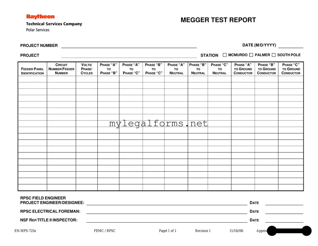
The Megger Test Report serves as a vital document in assessing the insulation integrity of electrical systems, ensuring safety and reliability in various projects. This form is meticulously designed to capture essential information, starting with project identification details such as the project number, station, and date. It prominently features the feeder panel identification and circuit numbers, which provide context for the test results. The report includes voltage measurements across different phases, allowing for a comprehensive evaluation of electrical performance. Specific readings are taken between phases A, B, and C, as well as between each phase and neutral, and between phases and ground. This data is crucial for identifying potential issues in the electrical system. The report also requires signatures from key personnel, including the RPSC field engineer and project engineer, ensuring accountability and thorough review of the findings. With its structured layout, the Megger Test Report not only facilitates clear communication of test results but also plays a critical role in maintaining compliance with safety standards.
When filling out and using the Megger Test form, there are several important considerations to keep in mind. These key takeaways will help ensure accurate reporting and effective use of the form.
By following these guidelines, users can effectively complete the Megger Test form, contributing to the safety and reliability of electrical systems.
Security Guard Report Example - The report ensures that all critical incidents are promptly reported to the supervisor.
The California Motorcycle Bill of Sale form is a crucial document that records the transfer of ownership of a motorcycle from one party to another. This form serves as proof of the transaction and can help protect both the buyer and the seller in case of future disputes. For a comprehensive guide on how to complete it, you can visit californiadocsonline.com/motorcycle-bill-of-sale-form, which offers valuable resources to streamline the buying or selling process.
Shower Sheets for Cna - Residents can be monitored for a variety of skin issues, such as bruising and rashes.
The Megger Test form is essential for documenting electrical insulation resistance tests. However, several other forms and documents often accompany it to ensure comprehensive reporting and compliance with safety standards. Here’s a brief overview of these important documents.
Using these documents in conjunction with the Megger Test form helps ensure thorough documentation and enhances safety and compliance in electrical work. Each piece plays a vital role in maintaining high standards in electrical testing and maintenance practices.
When filling out the Megger Test form, attention to detail is crucial. Below is a list of practices to follow and avoid, ensuring accuracy and compliance.
Following these guidelines will help ensure that the Megger Test form is filled out correctly and efficiently, minimizing the risk of errors and misunderstandings.
Filling out the Megger Test form requires careful attention to detail. One common mistake is failing to include the project number. This number is essential for tracking and referencing the test results later. Without it, the report may become lost in the shuffle, leading to confusion and potential delays in project timelines.
Another frequent error is neglecting to specify the circuit number or feeder number. This information is crucial for identifying which circuit the test pertains to. Omitting this detail can result in misinterpretation of data, especially when multiple circuits are involved in a project.
People often overlook the date section as well. Proper documentation requires a clear record of when the test was conducted. Missing this detail can create issues in accountability and may complicate future inspections or audits.
Inaccuracies in the voltage, phase, and cycle entries can lead to significant misunderstandings. Testers sometimes misread or misrecord these values, which can affect the assessment of electrical systems. It is vital to double-check these figures to ensure they reflect the actual test conditions.
Another mistake occurs when testers fail to fill in the results for all phase comparisons. Each phase must be documented to provide a comprehensive view of the electrical system's performance. Incomplete data can lead to an inaccurate understanding of system integrity.
Additionally, the signatures of responsible personnel are sometimes missing. The RPSC field engineer, project engineer, and NSF representative all need to sign off on the report. Without these approvals, the document lacks validity and may not be accepted during reviews.
Lastly, it is important to note that using outdated forms can create confusion. The Megger Test form should always be the most current version. Outdated forms may lack necessary sections or updates that reflect current standards and practices. Always check for the latest revision before filling out the report.
| Fact Name | Description |
|---|---|
| Project Identification | The form includes a project number and station, which helps in organizing and referencing specific tests conducted at various locations. |
| Date Format | The date is required in a specific format (M/D/YYYY), ensuring consistency in documentation and record-keeping. |
| Voltage and Phase Information | Details about voltage, phase, and cycles are recorded, which are essential for assessing electrical system performance. |
| Grounding Measurements | The form captures grounding measurements for each phase, which is critical for safety and compliance with electrical standards. |
| Signatures and Approvals | Signatures from the RPSC field engineer, project engineer/designee, electrical foreman, and NSF representative are required, indicating oversight and accountability. |
MEGGER TEST REPORT
PROJECT NUMBER
PROJECT |
|
STATION |
DATE (M/D/YYYY)
MCMURDO 
 PALMER
 SOUTH POLE
FEEDER PANEL IDENTIFICATION
CIRCUIT
NUMBER/FEEDER
NUMBER
VOLTS/
PHASE/
CYCLES
PHASE “A”
TO
PHASE “B”
PHASE “A”
TO
PHASE “C”
PHASE “B”
TO
PHASE “C”
PHASE “A”
TO
NEUTRAL
PHASE “B”
TO
NEUTRAL
PHASE “C”
TO
NEUTRAL
PHASE “A”
TO GROUND CONDUCTOR
PHASE “B”
TO GROUND CONDUCTOR
PHASE “C”
TO GROUND CONDUCTOR
RPSC FIELD ENGINEER |
|
|
|
|
|
|
PROJECT ENGINEER/DESIGNEE: |
|
|
|
|
DATE |
|
RPSC ELECTRICAL FOREMAN: |
|
|
|
|
DATE |
|
NSF REP/TITLE II INSPECTOR: |
|
|
|
|
DATE |
|
FEMC / RPSC |
Paget 1 of 1 |
Revision 1 |
11/16//06 |
Approved by Wayne L. Cornell |
||